There is a lot of potential in solving mechanical problems with information systems, rather than using complicated mechanical solutions. For instance, hydraulic automatic transmissions and differential.
The mechanical solutions are always really interesting and clever, but digital systems are much more flexible.
Really cool video on the mechanical ignition timing control in a delorean to control emissions. Explanation of ignition advance at the end: https://www.youtube.com/watch?v=ge1GwepqtK0
"The linkage to change the pitch of this rotating blade is way too complex! Can we simplify it somehow?"
"How about we just add a simple device that associates the pitch of the blade with the torque, and let a computer figure out how to spin the motor to get the pitch we want? No linkage!"
I'm still not getting it. Wouldn't the pitch of the two sides be the same so how would that be useful? How do you control the pitch of two blades with a single motor?
Look at the hinge picture. See how the two hinge pins are parallel? Now imagine the blades turning 180 degrees. The hinge pins will now be at the "opposite" angle to before, despite that the blades are symmetrical so identical at 180 degrees to 0 degrees.
So at 0 degrees, increasing torque will, say, increase pitch of the "right-hand" blade while decreasing pitch of the "left-hand" one. But at 180 degrees it will be the opposite. This has the presumably beneficial effect of allowing the craft to climb by simply increasing rotor speed steadily (it will "wobble" a bit but in a spiral fashion which will let it climb without too much inefficiency). Put another way, this means that increasing torque at 0 degrees but decreasing it at 180 degrees allows an asymmetrical pitch to be maintained at a rotational speed which can be seen as constant (over the long term).
In other words, your intuition falls down because the mechanism is not as symmetrical as your brain wants it to be at first glance. Symmetry is an intuitive and attractive for mechanical systems, but it is actually limiting in many cases, and this is a great example.
In an old-school helcopter you have, say, one main rotor with a vertical shaft, and one tail rotor with a horizontal shaft. Each of them has complex control mechanisms implemented in hardware: the main rotor has swash plates, and so does the tail rotor (or it has variable speed). The pilot controls the system in a direct and even crude way: a side stick adjusts blade pitch, sometimes via a simple cable linkage. Throttle is kept quite stable much of the time.
In this newfangled bird, we use some combination of GPS sensors, an input which is presumably a touchscreen (with all the associated latency, plus wireless), and a speed controller which has to adjust multiple times per revolution of the rotors. For some information on why this is tricky, start here: http://en.wikipedia.org/wiki/Nyquist_frequency
The information is the position of the rotor, pulled from the motor sensors. The control is the pulsing of the motor's torque at the right position to increase lift in a particular area of the rotor's arc. Informational control simply means you are pulling information out of the system to better drive the system itself.
The hinge that connects each blade to the rotor is angled with the same pitch, but on opposite sides of the rotor, like this:
------/ || /------
When the rotor applies more torque than the current angular momentum of the blades, the blades lag behind the central hub, pushing them the same direction against their hinges. On one side, that increases the blade pitch. On the opposite side, it decreases the blade pitch. The motor could also apply a slight braking force, to pitch the blades in the opposite direction.
The flight computer determines the correct timing at which to apply more oomph to the drive motor, which translates to the same effect as a mechanical swashplate due to the angled pins. The total energy imparted to the blades over a single rotation remains the same as with a motor operating at constant torque.
One disadvantage is that you will need a motor that is capable of applying more maximum torque, because you won't be running it at 100% all the time, but with a sinusoidal power level that will go both above and below that steady level. The other disadvantage is complexity in the computer controlling the motor. The advantage is mechanical simplicity.
Didn't you read the article and watch the video? There is a sinusoidal signal added (i.e. up and down) that matches the rotation of the blades and controls the hinges on the blades. So the signal can be high when the blade is on one side of the vehicle then low when the blade is on the other side. Or vice-a-versa if the control system wants to go the other way. Both blades tilt the desired direction when they are on the desired side of the vehicle. The video is quite good and shows the blades hinging different directions on different sides when the signal is applied.
The second motor and rotor provides vertical thrust and torque compensation only. It spins the opposite direction to the upper rotor. It does not steer the vehicle.
I assume you mean the motor rotation angle. It's probably not a brush motor, but a 3-phase synchronous motor. That means instead of having a commutator to apply the voltage to the coils, a computer switches some FETs to apply the voltage. In the simplest case, the rotor is assumed to follow the applied voltage waveforms. In a more typical system, the rotor position is estimated from the applied phase voltages and measured currents (usually via PLL or a sliding mode observer).
If you mean "how do they determine the blade pitch?" then the answer is that they don't need to. The controller - weather that's a computer with inertial sensors, or a person watching it - will just manipulate the amount of torque variation until it gets the response that it wants from the copter. Much like you don't actually need feedback of your cars gas pedal position so long as you have vehicle speed feedback.
Electric motors remove a lot of the complexity in powered-lift flying machines. As soon as your power/endurance requirements demand a combustion engine, you also have to manage the complexity of a piston engine or turbine (jet) engine.
This means either including a crankshaft and optionally a system of gears to route the rotational power along the axes you want the rotation in, or ducting the output of a jet turbine in some way that drives the rotors. In addition, there are different limitations with regards to the time required for a given change in RPM as compared to an electrical motor.
My impression is that a lot of the complexity in conventional helicopters (and flying machines in general) stems from the limitations of combustion engines. There's a reason that you very rarely see vectored thrust in conventional airplanes, for example.
Of course, if batteries and electric motors become sufficiently powerful, this changes the dynamic and it will become possible to design electric aircraft that re-evaluate the traditional design restrictions. This is one of the reasons that the rapid progress of electric cars is so exciting.
I don't think a hybrid like what you suggest is practical.
Locomotives need lots and lots of torque at zero and low speeds. This would otherwise necessitate a huge transmission. Plus, the weight penalty for a train locomotive isn't nearly as severe as it is for any kind of flying craft.
Other commenters have mentioned a hybrid system, with a relatively small electric motor that generates just the instantaneous torque changes needed for the control system, but the majority of the power is supplied via direct mechanical linkage as in today's helicopters. That might be viable, but I'm not sure. The weight and complexity penalty for the old control scheme isn't so bad when scaled up, but is really bad when scaled down.
So a hybrid scheme (like in a Prius) might be practical, by my estimation.
Probably not, for the same reason that a quadcopter doesn't really scale to full size. The inertia effects of larger rotors make changing the speed of the rotors within a rotation much harder.
With full sized helis, it takes a long time to spin up the rotors to speed before the pitch is changed to take off.
Well the critical difference here is that changing blade speed is not needed or desired. They just need to change blade torque, which would apparently immediately cause a change in blade pitch.
I don't see a specific reason why this wouldn't scale. I do wonder what changes in load do to the system though. If it can't handle changing loads without messing up the blade dynamics, it would only work for fixed payload systems like camera platforms.
You can use an electric motor. We can easily make extremely high power electric motors (see: CNC machines and Diesel trains), and power storage will continue to improve.
The added cost of batteries at even today's prices could be worth it for the decreased mechanical complexity of the rest.
If all we need to do is change the torque of an electric motor, that can be done essentially instantaneously even at high power levels.
Power storage may continue to improve, but it will take a long time before you hit the energy density of fossil fuels; the difference between batteries and fossil fuels is something like a factor of 10 (actually greater than that, but electric motors are more efficient so let's say 10 for the sake of argument), and it's improving much more slowly than Moore's Law, doubling maybe once every 10 years. That means if those trends continue (and there's no guarantee they will), you're looking at 30-40 years before the energy density allows electric helicopters to be competitive with fossil fuel powered.
For cars, energy density isn't quite as important, as the weight of the car is not the dominant factor in its efficiency (it does have an effect, but the aerodynamics, engine efficiency, transmission efficiency, tires, etc. all make a big difference too). But for a helicopter, every pound you add to the batteries is another pound you have to lift, so energy density of your power source is quite important.
So, if trends hold on battery technologies, it will come about eventually; but I would put money more on the decades timeline than the years timeline.
I don't think scaling this up is a question of inertia it is more a question of weither a material exists that can be used in those flexural joints with much higher loads.
This is a material science question. A material may exist that has the right combination of flex, strength and lets also not forget durability. I am a mechanical engineer and crack propagation and cycle fatigue would be a major concern for a joint like that at large loads. There are all kinds of amazing tricks material scientists know how to play to combat these types of problem.
I think this could be scaled up if material to make those flexure joints exist.
You could couple a high power combustion motor with a relatively low power electric motor via a differential, and have the electric motor do the 'high frequency' modulation the combustion motor is incapable of.
With a regenerative approach, you'd probably need very little net electric power.
Sure it would work. It only needs a variable clutch on a standard engine and the motion on the blades is very slight and mostly balanced, so the torque difference should be pretty manageable.
Depending on what you mean by scaling up. There have been single man vertical take off and landing (VTOL) vehicles that have two rotors and require no variable pitch for directional control so they are even simpler then the system in this video since the 1950's! The first such vehicle was the Hiller VZ-1, dubbed the "Flying Platform". If you are in the bay area you can go check a real one out at the Hiller Aviation museum next to the san carlos airbort (30 minutes south of sf). Or enjoy watching this video...
Directional control is achieved by leaning, the gyroscopic forces from the dual rotating blades creates inherent stability without any feedback system. They are like segways of the sky. Reports say it only took 20 minutes for a non pilot to learn how to fly it. These machines are incrdible and I don't understand why more hasn't been done with them.
A late 1970's version called the williams x jet WASP added a cruise missle turbojet for more horsepower, and was coined the "flying pulpit".
As an aside I think a vehicle like this could be developed today and fall under the FAA ultralight powered vehicle classification (weighing less then 254 pounds and carrying less then 5 gallons of fuel). This classification doesn't require you to have a pilots license!
People here might also be interested in the Mosquito Air helicopter as well. It falls into this ultralight classification and is a kit you can build in 200-300 hours. It costs about $30,000...
Big rotor = big moment of inertia = more energy lost on accelerating it and slowing it down each time. At some point it's better to rotate it at constant velocity and change pitch independently.
That's what I was thinking. That would require electrical motor control of the blades. Maybe turbine generator for power source. I would imagine this kind of pulsing would cause severe fatigue on the parts if they scale up too large.
The parts will cycle back and forth exactly as much as they would in a traditional helicopter, and there are fewer comparatively small parts. It would likely be stronger and more fatigue resistant than current methods of controlling blade pitch. We can program the motor to change torque as smoothly as we want.
It would probably work but I'm guessing the overhead of the extra actuators is much smaller at full size, so this may not be as helpful as at small sizes.
The complexity of the conventional helicopter method is not only providing control, but also a considerable amount of safety by enabling autogyro capability. This lack of autogyro is already restricting the quadrocopter setup to "let it crash" dimensions and the same well be true for this admittedly very clever duocopter.
This is such a neat idea, but I wonder if it suffers from vibration problems. Because the blades are mounted on pivots, whenever you've commanding differential pitch, the high angle-of-attack blade will incur more drag and so lag slightly more than the low angle-of-attack blade. Thus the blades won't be exactly opposite each other anymore, creating vibration. Perhaps the blades are spinning so fast this is not a big deal? Probably would be if you scaled up though.
Vibration only becomes a problem when the scales of the drag/lag and rotational frequency are similar. My gut feeling is that this will only happen when your lift-to-drag ratio is close to 1, so not in any meaningful case.
I don't think the force on the rotor would change direction fast enough to cause a vibration. It would be more like a constant push relative to the intended tilt, or a slowly spiraling wobble.
Reminds me of PWM [1] on old PC speakers. Many old computers (e.g. of the 286 era) had a speaker that was only able to generate square tones. By controlling the start and duration of the pulses, programmers could generate sounds that were a lot more rich than what you would expect from "plain" square waves [2].
In a way this is similar: they start with two actuators that seem very limited in what they can accomplish: you can only speed them up and down. By modulating the speed of both motors in sync, they are able to control that cheap rotor mechanism they came up with, achieving 6DoF [3]
I wonder if this will cause some parts of the motor to heat up more; since the blade is 1:1 rotations with the motor then driving more torque (power) during certain phases of the cycle will put more watts on certain coils.
It's a cool idea. Human size helicopters would love to avoid all that blade-pitch complexity. :)
Couldn't that be addressed (if a large enough effect to be a problem) by just having the body of the vehicle spin at a low rate, like less that 1Hz. With appropriate sensors this wouldn't be a problem[1]. More to the point, there shouldn't be any need for sustained constant "cyclic" input anyway, in normal maneuvering.
[1] an axially-symmetric imaging system could compensate easily, e.g. a panoramic system.
Very clever! I hadn't fully understood the mechanical complexities involved in a standard single-rotor helicopter. I just thought that they were hard to fly manually (which made me very confused to see all the computer-controlled quadrocopters - why didn't they use just one rotor?)
Well the issue isn't just that they're hard to fly or that they're mechanically complex - the issue is that they're both. So you crash often (when flying models) and crashes are expensive. This makes it a very expensive hobby.
The issue when flying is that they balance as if they are on a ball. You need to constantly adjust the controls to stop from "falling off the ball". Go the wrong direction and you speed up the rate at which it falls. When it is facing away from you, that's not very hard. When it is facing towards you everything is backwards. When you are turning, the correct direction to stay balanced is constantly changing.
Automated systems can do this automatically for you though, so a drone-like autopilot in a standard helicopter could make them as easy to fly as quadcopters. Traditional helicopters are still mechanically complex though. This system looks to fix that. And this would be more efficient than a multirotor.
At first viewing of the video I didn't understand why the body doesn't spin around with one rotor and a pair of blades. That was some magic! Then looked at the picture again and saw another rotor underneath. Pretty neat to have two rotors counteracting each other.
Seriously, why?
Injection molding has far lower cost, higher quality, and you're talking about things that are very cheap and easy to ship.
What does 3D printing bring to this?
Injection molding is on the order of 10,000x more expensive if you only need a single part.
I'm currently on a quest to design highly functional robots that can be made with just a 3D printer and a minimum of external parts - so far only bearings, motors, drive belts, batteries and electronics are the non-printed parts needed. I make everything so that it fits together by interlocking or with minimal use of some coarse printed fasteners.
Since nothing needs to be bought from the store that won't be useful if the design changes, it is trivial to iterate and build a newer version.
My hope is that with developers worldwide working on improvements, injection molded versions of the parts would become obsolete before the mold was even cut.
When it comes to manufacturing, 3D printing is a whole different ballgame. No other manufacturing technique can make so many complex parts without human intervention. This means it opens up all new possibilities for how we manufacture things - like continuous iteration of shipping hardware.
Well, parts made in a powder bed printer don't typically have nearly as much grain, if any. I'm a big fan of that style printer in the future, so one solution to the problem is to use those instead.
For typical FDM/FFM printers like the hobby ones you see everywhere, there are chemicals that can be used to smooth the print out.
I use my parts for robot prototypes where the function of the part is more important than cosmetics, so I don't worry about the grain. If I want a nice part though, I can use very fine layers.
that is a horrible article, considering the picture they are using is ripped off of a reprap blog on smoothing abs prints using acetone vapors. http://blog.reprap.org/2013/02/vapor-treating-abs-rp-parts.h.... (I'm actually a member of Fablocker, so I'd seen those squirrels before)
on that note though, from my experiments, acetone vapor bath does seem to strengthen abs prints some, cause it melts the surface together. Not terribly big effect, but it actually helps a lot for low infill parts and stuff.
You can give the parts a vapor bath, but you lose some of the exactness. The longer you do it the smoother the part but the more it loses it's dimensions. You are basically melting the plastic with fumes.
1m square deskspace requirements and fast tooling in software, rather than thousands of pounds and new metal every time you want to change a detail.
Injection moulding is only lower cost when you want to buy something that is already mass manufactured or millions of identical things. Up to about 10,000 units, 3d printing is cheaper.
At-home 3d-printing uses shitty materials and has terrible precision. If you don’t want to go all the way up to making expensive metal tooling and doing injection molding, you can sill get much better results from CNCing some material and then using resin casting than using a 3d printer: http://lcamtuf.coredump.cx/gcnc/
Well, I've had my 3D printer for over 3 years, and ran design and machining for an engineering shop for 7 years, and I have to say I disagree.
How do you define "terrible precision"? Is there a fixed scale in which precision goes from "terrible" to "okay" to "very good" to "excellent"?
If I'm building a telescope mirror, I guess I just ask the manufacturer for "excellent" precision, and they know what to do?
How do you classify "better results"? It is the smoothness of the part, the strength, or the cost at 5, 50, or 100,000 units? Why do resin casting when I can do lost wax casting?
Can you tell me, which manufacturing method is the best?
Oh sorry, we haven't talked about what we're making yet. Seems any discussion of tools to fabricate things is senseless until we've established what we want to make.
I'm designing a robot anyone can make at home. I mean actually, that is what I am doing as I type this comment. (well, I was designing it. It's printing now.). I want a robot that can be customized by the user. I want it to be as cheap as possible for someone who does not have access to anything more than basic electronics and a 3D printer. I want people to be able to design upgrades and test them.
Do you think I should design it so I can CNC molds that I use for resin casting? That is, after all, what you suggested.
But then, when I CNC something it takes a loooong time. First, I would design a part completely differently if I was going to CNC it versus print it. And if I was going to CNC a mold for casting, I would design it a third way still. If I am going to CNC a mold, I need to figure out where the parting line will be, and how all the molds will fit together. Some parts are impossible to cast, so I have to make sure not to design the part so as to be impossible to make with my chosen method.
Once I decide to CNC a mold, I need to source raw material that is as big as my part, but not so big that I waste a lot of material. I'll need some way to grab it in the CNC machine, so typically I choose material a little taller than my part. Ultimately it depends on how I specifically choose to make this part, and isn't strictly defined by the part's size or function.
To order raw material, if it was on short notice, I would need to go to the material store. In silicon valley across from the Fry's off Brokaw there is a place called Campbell Metal. Campbell metal is a large warehouse full of people and metals. The metals are sorted by size, shape, and length, and the people who work there tend to those materials - taking orders from the front office and cutting short pieces out of long bars. The cost of my material includes the cost of living of those people and the cost of the overhead for the large warehouse all that material is in.
Once that material is on order, I would need to program the machine to make the part. That involves figuring out the steps in order that I will use to take that raw block of material and turn it into my part. Simple parts may have 2 or fewer steps. Most have at least 3. Each one is a separate program. Once I've manually defined the toolpaths to use to make the CNC machine hollow out a block of steel or aluminum, including choosing how to send the tool into the metal, how fast to spin it, how quickly to move it, what depth and width of the tool should make a cut, I can begin to set up the machine to cut the first step. This involves taking all the right tools from the shelf, out of hundreds of possible tools, and loading them into one of the 24 tool pockets on our machine.
The machine, a HAAS VF-2SS, cost my employer around $90k. They sell a couple million dollars a year in custom made tools, so they could afford to pay this off over 5 years. I was pretty lucky to get my hands on that every day.
I could go on about the casting (get a scale, mix up material by weight, cast it), but I hope you see my point.
There is no "best" technique for "makin stuff", because every part is different. When I designed a waterproof housing that was sent 3km underwater to deal with the Deepwater Horizon oil spill, it was made from super thick aluminum with steel reinforcement. But when I designed the power button for our custom android tablet, which included software I wrote to help lift a nuclear cooling tower, I used dinky Delrin plastic for the part. There is no one best material either.
3D printed parts have certain properties. 3D printers have some limits. But what they lack in quality they often make up for in simplicity. If I had decided to print the part above instead of cast it, I'd have just made sure the thing was full and then hit "print". When I need to change something about the design, like I did this morning, I repeat that process. Iteration is a million times easier with 3D printers, which means designers can spend more time refining their parts.
For the robot I am designing, anyone with a 3D printer and the most basic of electronics can build a robot. I know where 3D printers are strong and where they are weak, so I design my parts to take that into account. They are chunky, and I leave a lot of room for the wide tolerance of home printers, but the parts work.
My 3D printer, when poorly adjusted like it is now, can hold maybe 0.040" of tolerance on a part. When I worked at the machine shop, my day to day realm was within 0.005" tolerance. On a critical part like a bearing seat, we'd add another zero to that. But there are guys making semiconductors with moving parts like DLP chips that would laugh at those tolerances. Even the guys cutting gears on their worst day would have bested my best try, because our basic $90k CNC machines had laughable quality compared to the "real" stuff.
Everything is relative. Even hand carved bricks can build a pyramid - with the right designer.
First things first, I never suggested that you personally should use any particular fabrication method for any particular purpose. In the chain of ancestor comments to my post, none of them have anything to do with you specifically.
With that said, I don’t think you looked at the resource I linked, which has some great advice for using a CNC mill to make high-precision parts via resin casting. Nothing in its advised method involves milling metal. The design involved might be slightly more difficult than designing parts for 3d-printing, but it’s not inordinately more difficult.
I personally find home-3d-printed parts to be very slow to print, expensive to print, ugly, brittle, and entirely ineffective for many things I’d want to do with them (art projects, mechanisms, housings for electronics projects, small pieces of furniture, etc. etc.). Everyone I know who has tried to do 3D printing at home spent much more time fixing and babysitting their machine than actually making stuff (and most were ultimately unsatisfied with the quality of their prints). The process is by no means “simple”.
- For a one-off part, it’s often possible to directly CNC mill something out of plastic, wood, or some other material that is vastly superior in quality and can be made just as fast or faster than a 3d-printed part.
- Sometimes a few flat pieces of wood, sheet metal, or acrylic cut on a laser cutter or waterjet, or using manually operated tools is a better option than CNC milling something.
- For certain other parts, I’ve seen reasonable results ordering from Shapeways or some similar place.
There might well be particular cases where home 3d printing is the best answer, but nothing that I’ve personally run into.
I should note, I have seen that site before. Looking at your comparison pictures, I have a couple of thoughts:
1) I am very aware that machining and casting makes higher quality parts. My point is that for all mechanisms there comes a point where the quality is "good enough".
2) The printed gears you linked to have abysmal quality. My 3 year old printer has made vastly superior parts. See this thingiverse part, with many high quality print examples from home printers:
http://www.thingiverse.com/make:17409
I also used to be of the opinion that CNC machining was so superior as to render 3D printing useless. I looked at those stringy prints and said it would never be useful. But then, I slogged for years making CNC machined parts (see some examples of my parts here: http://www.tlalexander.com/files/portfolio.pdf ) and eventually decided to buy a 3D printer. I make more stuff now than I ever did when I had daily access to a CNC.
But as far as quality - notice how that stringy gearbox you linked to still seems to work? Sure, one is more photogenic, but the goal of a gearbox is to transmit power not win a beauty contents. Meanwhile I have been using a printed gear on my 3D printer's extrusion system for over 2 years with no sign of failure. The application is low speed but medium torque, and I see no wear or signs of weakening. The printed gear satisfied the requirements of the mechanism.
When I think of 3D printing, it reminds me of manufacturing in the 1940's. Parts were clunkier then, like the seat hinge on an old Volkswagen Beetle. But clunky works - often better. Newer techniques might make smaller hinges, but the one from the old beetle still works well. Sometimes higher quality isn't necessary to make something. A designer may choose to make something clunkier so that it can be made at home on a basic printer.
You seemed to suggest that 3D printer is never the ideal way to make something, but of course if I need the part as soon as possible 3D printing usually is.
My long rant about CNC machining was meant to highlight the huge amount of labor involved in machining things. It takes a lot of human skill to write a CNC program (I do expect that to eventually change though) and more labor to set up the machine to get the first part made. In the time it would take me to CNC something I can print a part while I eat a sandwich or run some errands.
Of course 3D prints are slow to produce, but that is counteracted by the fact that it takes less of my involvement to get the parts made. It takes less overall effort to produce a part by print than by machining.
I mentioned metal but the entire story I wrote applies to plastic machining as well - just replace "Campbell Metal" with "Professional Plastics". They're both across from the Fry's off Brokaw.
I totally don't expect most people to have "run into" a time where home 3D printing is best, but you can still do thought experiments. 3D printing is far more accessible to most people than CNC machining is. As home machines get better and we gain more critical mass of users, we will see more designers who take advantage of the stuff that can be made at home. That's what I'm doing with 3D printable robots, and luckily I have a good intersection between people who want to make robots and people who own a 3D printer.
I would say the two key differences between 3D printing and machining is that 3D printing takes zero skill to operate and zero or near-zero labor. Not all home machines have delivered on the ease of use promise of course, but that is an issue with the machines, not the process.
My point is, no other manufacturing technique is well-suited for use at home aside from perhaps laser cutting. The value in printing is of course not the quality of the parts, but the fact that it is a type of manufacturing accessible to consumers. Imagine if Dyson provided printable replacement parts for example, and you can begin to see the value.
Every manufacturing technique has trade offs. A single print takes longer than machining a single part, but with less set-up. Time to first part can often be lower on a 3D printer.
Wrong, wrong and wrong. I'll start with the last "wrong" first. The third wrong (for your statement which only includes two issues) is for the typical, and ill thought process of technology. That it won't change, and it won't get better. It will, and it's doing so by leaps and bounds. 3d printers are quite literally coming out with new processes and equipment every single day. There have been a number of announcements in just the last few months that make it appear that even using metals for at home printing at an affordable rate may be possible in the next five years. There is such a fast rate of change and innovation, it's a bit silly to think that your comments on bad quality and materials won't change within the next year (if those comments were correct, they're not.)
As to materials, literally, every month, there are new materials coming out. At this point, I can use my desktop reprap to print ceramics, PET, Nylon, ABS (to just name a few), and all sorts of hybrids/specific compounds of these plastics designed for 3d printing. Nylon, PET, ABS are good enough for probably ~90% (very rough guess, sorry) of most of the plastic products in your home, it's probably good enough for most of the products I (and many others want to make).
As to precision, that's also quite wrong. The printers are quite precise. They're not as precise as the $75,000 CNC Mill that will get me .001" accuracy, but the truth is that most people don't even need .01" accuracy. And my printer cost me $500, quite a large cost premium there in terms of accuracy (ignoring the importance of cutting metal at this time).
As to doing CNC at home. Even a quite crappy homemade CNC mill, built on a real "mill"(something like a g0704) (not the laughable (to me) desktop mills that have come out recently, which are glorified dremels using similar methods of driving the axis' as a 3d printer, which you can cut aluminum at atrociously slow rates) is going to cost you at least $3000 (machine tools are expensive, not just because of the actual mill, but all the tool holders, bits, cutters, precision vises, calipers, etc. etc. that you also need to make it useful). So yes, a CNC mill is great for alot of things, but that homemade CNC mill isn't really going to hold .001 accuracy either, unless you spend a lot of time working on it and you really know what you're doing.
I'm not going to continue on with this argument, but it seems like your view of 3d printers and CNC milling is quite naive.
My $1500 home CNC will give .001" of an inch of accuracy. You'd be amazed how much errors in the .01s of inches stack up into unusable parts (try doing inlays with wood).
You are quite right that the cost of operation is quite a bit higher though. Bits, collets, spindles, etc really add up. Even with wood, all the tooling is made of solid carbide.
subtractive machining has its benefits though. While printing can make some unattainable shapes, subtractive machining gives a nicer variety of materials, and can be faster.
as to the more mature technology now, CNC definitely has 3D printing beaten, at both scale and precision. Hopefully soon, we'll be able to 3D print carbon fiber parts and then we'll have a real 3d printing boom.
Don't get me wrong, I'm also a machinist, and I do use subtractive machining quite a bit. And I'm guessing your CNC machine is a router, not so much a mill (to make life easier, I'll classify a mill as having a much larger Z-axis movement, and built to deal with harder to machine materials (steel essentially.)) And in that case, it's much easier to get a router to hold smaller tolerances than something that's designed to handle steel. Now I could be totally wrong, and if so, props to you, you got a deal. But really, even the cheap chinese mills (again, talking about something like the Grizzly g0704, maybe the Sieg X2) I've seen that (sans CNC equipment) start at around $1000. And once you add on ball screws, servos, and all the control hardware, you're pushing $1500 easily. And like you said, then you have to actually buy the tools you need to use it.
But while prices on CNC mills are getting cheaper, I'd argue that they aren't declining in price the way that 3d printers are (my reprap cost me $400, my makerbot clone $550). A mini-mill still costs more than it did 10 years ago, with very little improvements to what it does (better motors, electronics, that's about it.)
But to put it simply, I agree with you. Subtractive machining has it's place for sure, but so does 3d printing. But to say that 3d printing sucks, period, is just silly and ignores all the benefits that 3d printing provides. I believe in using the right tool for the job. Sometimes that's old school machining, some times it's 3d printing.
I'll add two quick, somewhat off topic points. It's now (apparently at least, according to GE) easier for them to additive manufacture turbine blades made out of inconel than it is to subtractive manufacture them. I've never had to machine inconel, but from what I've heard, it's quite the difficult thing to do, and most places that machine it, try to cast the part as close to net as possible to make as little machining as possible to do so. But this is something that truly shows the advantages of 3d printing that (might) be better than the traditional way of machining.
The other anecdote is my own. The other day, I was making a part, and for shits and giggles, I took the blueprints, made the part in CAD, printed it out on my 3d printer, and just the act of holding it in my hand and looking at it really helped me think about how to go about machining it out of steel. Most people think "On, CNC is easy, you just throw the file on the machine and it makes the part." It's not that easy, and I was just doing this part on a manual machine. But having that part in my hand really helped me make better decisions on how to best machine the part itself. I thought that was a neat little aspect of 3d printing that I would have never even thought of using it for.
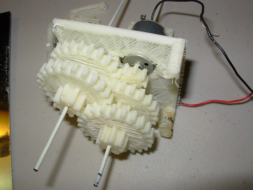
These other components look printable too. Right now I am making 3D printable robots that don't need any non-printed parts aside from motors, bearings, and drive belts (and batteries and electronics).
Thanks! Currently I'm working on delivering Flutter Wireless, which is at www.FlutterWireless.com.
The 3D printed robots will be for some tutorials we will be launching. Other than that, I've been continually procrastinating about making a website for my personal projects, but I have a lot. If you dig through my youtube account at the original link, I have some other project videos there.
Not currently represented online are some of the robots I have made, the Tesla Coil I made when I was in High School, and the gas powered hovercraft I made in 8th grade. :)